Environmental Engineering Reference
In-Depth Information
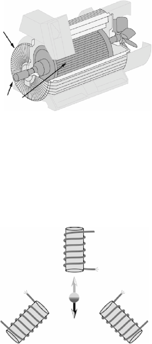
Stator
Rotor
Figure 7.6
Cut-away drawing of induction generator.
connected by aluminum end rings. The rotor has an iron core consisting of thin insulated steel lami-
nations with holes for the conducting bars. AC voltages across each pair of terminals create a rotat-
ing magnetic field and produce rotation in the center rotor, phase separation of 120° (Figure 7.7).
The rotating magnetic field induces currents in a set of copper loops in the rotor, and magnetic
forces on these current loops exert a torque on the rotor and cause it to rotate (as a motor). When it is
forced to rotate past the synchronous speed (900, 1,200, or 1,800 rpm), it becomes a generator. The
relationships of power, torque, efficiency, and rpm are given in
Figure 7.8
.
S
N
N
Figure 7.7
Schematic drawing of a three-phase AC generator. Rotating magnetic field produces AC voltages
across each pair of terminals; phase separation of 120°.
Search WWH ::

Custom Search