Environmental Engineering Reference
In-Depth Information
##&$
##&$
)!#%
#( '! &$
(!
""%!
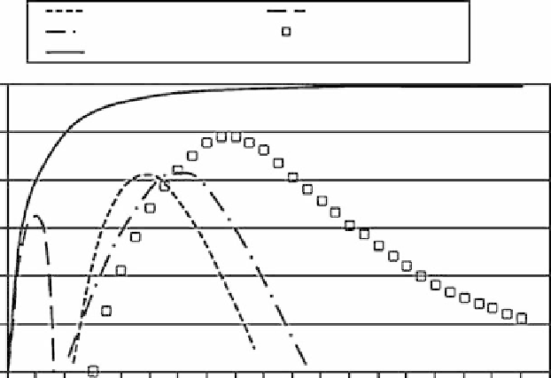
FIGURE 6.14
Experimental power coefficients for different rotors compared to the theoretical value: farm
windmill [31], Savonius [32], 100 kW Darrieus [33], 500 kW Darrieus [19], horizontal-axis wind turbine,
Carter 25 (data from
Figure 6.12
)
.
The three methods of regulating output are passive stall, where the wind turbine operates at fixed
rotational speed with fixed-pitch blades; active stall, where the wind turbine operates at fixed rota-
tional speed with adjustable pitch; and variable pitch, where the wind turbine operates at variable
rotation speed with adjustable pitch blades. The last method is the most efficient aerodynamically,
but the method of control chosen is always a trade-off between energy production and cost.
Control of rotor rpm using adjustable pitch includes full-span control, where pitch motors are
located in the hub; variable-pitch tips; and ailerons (flaps on airplane wing) to control aerodynam-
ics, even though it is not adjustable pitch. The last two have pitch motors in the blade. Now for large
wind turbines, the most common method is full-span control, although wind turbines have been
built with the other two control methods. The MOD-2 and MOD-5 had tip control.
Ailerons are moved to the low-pressure side of the blade to reduce lift, in contrast to flaps on
planes, which are moved in the opposite direction to increase lift. NASA-Lewis investigated ailerons
both theoretically and experimentally for application to medium and large wind turbines [34]. Zond
built twelve 500 kW units with aileron control, and they were installed near Fort Davis, Texas, as part
of the Utility Wind Turbine Verification Program [35]. However, after 4 years of operation they were
dismantled, with one of the reasons being the maintenance problems with the ailerons. Finally, there
was the Italian Gamma 60, 1.5 MW, wind turbine with fixed-pitch blades where the control was to
yaw the rotor. One problem with that is the difference in lift on the blade on each cycle.
There have been efforts to develop passive pitch control techniques that adjust the blade pitch
angle without a need for actuators [36]. One concept is the self-twisting blade in which the blade
spar at the hub is flexible, and the thrust and centrifugal forces on the blade cause it to twist to the
feathered position. United Technologies Research Center built a 10 m diameter unit with the two
blades (constant chord, no twist) attached to a flexbeam (
Figure 6.15
), which was attached in the
middle to the drive shaft. There was enough twist to provide torque for start-up, and pendulum
weights outside the plane of rotation moved toward the plane of rotation and provided proper
pitch angle for the run position, and also, the weights provided control at high winds by twisting
Search WWH ::

Custom Search