Environmental Engineering Reference
In-Depth Information
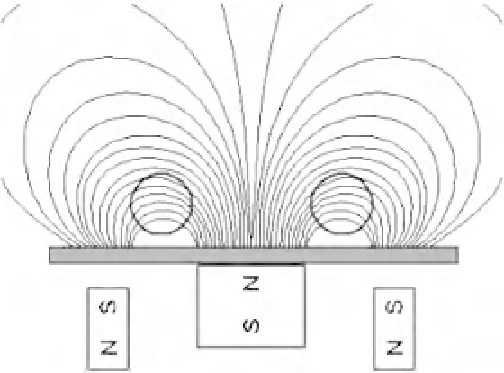
Figure 4.27
Magnetic lines of force in mag-
netron discharge. As a result of summation of
magnetic fields of two magnets of axial sym-
metry, the total magnetic field has a maximum
of circular shape. Electrons may be captured
by this trap and do not partake in the ioniza-
tion processes at the cathode.
moment
μ
for this electron motion is
IS
c
D
1
c
ew
2
eE
z
r
2
H
r
2
μ
D
r
π
D
,
π
where
I
r
) is the current created by this electron,
r
is the radius of the
ring where the magnetic field has a maximum, and we use (4.138) for the electron
drift velocity. For the depth
U
max
of the potential well due to action of the magnetic
field this gives
D
ew
/(2
π
eE
z
r
2
U
max
D
.
(4.154)
For definiteness, we make an estimate for magnetron discharge in helium, being
guided by the electron temperature
T
e
D
3 eV. The criterion
ω
ν
gives in
H
10
16
cm
3
for the number density of helium atoms, which
corresponds to a helium pressure of
p
this case
N
a
3
1 Torr if the helium temperature is of
the order of room temperature. Next, the ratio of the depth of the potential well
U
max
to the electron temperature
T
e
is
U
max
T
e
D
3
2
eH
Mc
r
0
c
H
E
1,
and taking typical parameters of the magnetic trap for magnetron discharge,
H
D
100 G and
r
2 V/cm. Corresponding-
ly, on the basis of these parameters according to (4.141) we obtain
T
e
D
3 cm, we obtain from
U
max
T
e
that
E
z
3eV for
the electron temperature.
We note the principal difference between the magnetic mirror shown in Fig-
ure 4.26 and the magnetic trap of magnetron discharge. There is a low plasma