Chemistry Reference
In-Depth Information
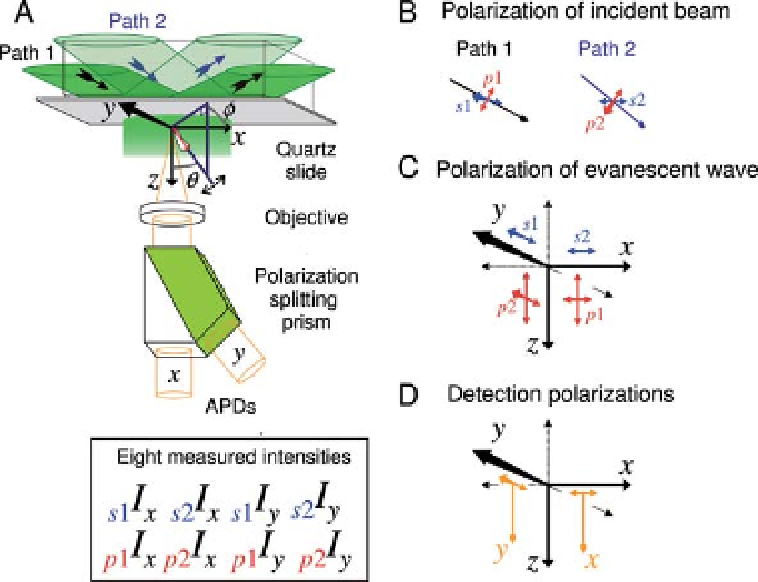
Figure 3.6 Geometry for a prism-type polarized
TIRF microscope. A, Paths of incident, reflected
and fluorescent emission beams and definitions
of detected probe angles. APDs are avalanche
photo diodes. B, definitions of incident beam
polarization. s-Polarized illumination is polarized
in the horizontal plane. p-Polarized illumination
is perpendicular to s-polarization. C, polarization
of the evanescent wave for each of the input
paths and polarizations. Note that p-polarization
leads to both transverse (downward) and
longitudinal (horizontal) components. D.
Polarizations of the detectors. The downward
colored arrows show the direction of fluorescent
light propagation. From Ref. [40].
time resolution. The raw photocount traces are corrected for the different intensities
of the illuminating conditions (partly given by Equations 3.2 and 3.3 above), different
sensitivities of the two APDs, the elliptical components of the p-generated evanescent
waves, and intermixing of the x- and y-polarization emissions by the objective
lens [50]. Corrected intensities are then
fitted by a model that predicts the polarized
fluorescence intensities based on the angular dependence of probe
uorescence
emission (Figure 3.7A),
, the
azimuthal angle around optical axis, and limited rotational mobility of the probe on
the subnanosecond time scale and, separately, on the microsecond time scale [20].
Also taken into account are the collinear absorption and emission dipoles (e.g. for
rhodamine or Cy3) and background intensity measured after photobleaching. Snap-
shots of these angular parameters are estimated every 40ms. A few hundred
photocounts per 10-ms time gate are typically recorded, leading to standard devia-
tions of the angular measurements of 5
-
15
[20]. Themain source of this uncertainty
is photon counting shot noise, making much higher time resolutions feasible at
higher laser intensities.
Because the dipole moments of the probe and the excitation and emission light all
exhibit C2 symmetry (rotating 180
about a central axis does not alter the structure),
q
, the axial angle between dipole axis and optical axis,
f