Image Processing Reference
In-Depth Information
Barrier electrode
Storage electrode
φ1
φ2
(a)
n
-
layer
n
layer
p
Silicon substrate
Charge
packet
Built-in potential difference
t
1-1
(b)
t
1-2
t
2-1
FIGURE 5.4
Two-phase CCD: (a) cross-sectional view; (b) schematic diagram of charge transfer.
The next CCD, which has two phases, is expressed as a proper mode for high-speed trans-
fer. Cross-sectional schematic diagrams of charge transfer and driving clock pulse are shown
in Figures 5.4a, b and 5.5, respectively. Two adjacent electrodes are connected and a built-in
potential difference is formed between paired electrode channels by introducing different
impurity concentrations in each channel. The electrodes with higher and lower channel
potentials are called storage and barrier electrodes, respectively. Pair electrodes are driven
by application of the same clock pulse, maintaining the built-in potential difference. Using
H
φ1
L
H
φ2
L
t
1-1
t
1-2
t
2-1
t
2-2
t
3-1
t
3-2
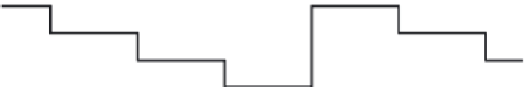
FIGURE 5.5
Driving clock pulse of two-phase CCD.