Image Processing Reference
In-Depth Information
First line
Second line
ird line
Fourth line
n
th line
(
n
+
1)th line
(a)
m
th line
Frame = field
First
line
Second
line
ird
line
Fourth
line
n
th line
(
n
+
1)th line
m
th line
Horizontal blanking interval
Vertical blanking interval
Time
(b)
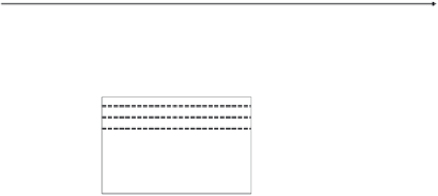
FIGURE 4.1
Progressive mode: (a) progressive scanning lines; (b) serial output and names of each part.
First line
Second line
ird line
Fourth line
n
th line
(
n
+
1)th line
(a)
m
th line
Frame
Second field
First field
First
line
ird
line
Second
line
Fourth
line
m
th line
(
m
-
1)th line
Horizontal blanking interval
Vertical blanking interval
(b)
Time
FIGURE 4.2
Interlaced mode: (a) interlaced scanning lines; (b) serial output and names of each part.
Although the above example is interlaced by two fields, there are cases constructed
using more fields, depending on the kind of system. Especially, CCDs in digital still cam-
eras have a tendency to employ the interlaced mode with many fields, since many pixels
are necessary for high-resolution sensors that have enough time to be operated for read-
out. The resolution of a still image does not depend on the number of the scanning field,
because exposure time is controlled by an optical shutter to capture in progressive mode.


