Image Processing Reference
In-Depth Information
An organic image sensor is one way of overcoming the above limits of silicon image
sensors. There are two challenges for 3-Tr pixel configuration. The first is to make exten-
sive changes to improve sensitivity and dynamic range using organic materials as the
photoconversion part. The development of the material itself and the fabrication process
in combination with the silicon process are included. The other challenge is to overcome
the disadvantage of 3-Tr pixel configuration by combining it with organic photoconductive
material and creating a new pixel configuration with a noise reduction circuit by using
feedback reset.
61
Organic photoconductive materials have been investigated,
62
but it is indispensable to
pursue low-noise-readout techniques to put into practical use.
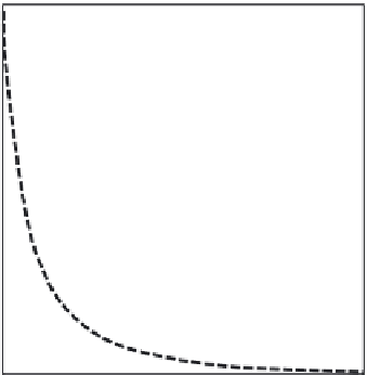
Some organic materials have an absorption coefficient63
63
one order of magnitude higher
than that of silicon in the visible region, as shown in Figure 5.73. Therefore, the thickness
of photoelectric conversion film (organic photoconductive film [OPF]) can be decreased
to <0.5 μm, while in ordinary PDs silicon image sensors are 3-4 μm thick, as shown in
Figure 5.74. This makes it possible to remove the light-shielding layer, giving rise to a wide
pixel aperture and a wide incident light angle, as shown in Figure 5.74.
Figure 5.75 is a schematic cross-sectional view of a typical pixel region.
64
It consists of
micro lenses (OCLs), on-chip color filters (OCF), protective film, the top transparent elec-
trode, OPF, and the bottom pixel electrode directly connected to CMOS circuits. Because
of the absence of a light-shielding layer, the ideal aperture ratio of 100% is realized. By
applying a positive voltage (
V
top
) to the top transparent electrode, holes of photoconverted
charges are collected by the bottom pixel electrode connected to the pixel circuit.
The genuine characteristics of the OPF, QE, and dark current are shown in Figure 5.76.
QE measured at a wavelength of 525 nm increases in proportion to
V
top
up to 10 V, beyond
which QE saturates. Since the dark current behaves as a monotonously increasing function
of
V
top
, the highest SNR is obtained at 10 V.
As mentioned above, an OPF CMOS sensor has 3-Tr pixel configuration and without any
countermeasure, it has a large kTC noise of 38 electrons.
62
To solve this problem, a column
100
90
80
70
60
50
OPF
40
30
20
Si
10
0
400
700
800
500
600
Wavelength [µm]
FIGURE 5.73
Absorption coefficient of silicon and OPF. (Reprinted with permission from Isono, S., Satake, T., Hyakushima, T.,
Taki, K., Sakaida, R., Kishimura, S., Hirao, S. et al.,
Proceedings of the 2013 IEEE International Interconnect Technology
Conference, paper ID
3030, 2013.) Copyright [2013] by the Japan Society of Applied Physics.