Image Processing Reference
In-Depth Information
Output
Pixel
V
ss
Load
Tr
φR
RST
V
LG
Light
TX
V
d
Drive
Tr
Vertical
signal
line
Tr
RS
(a)
PD
FD
Q
sig
(1)
Exposure completion
0 V
RST: OFF
RS: OFF
TX: OFF
Q
noise
3 V
Q
sig
(2)
FD reset
0 V
RST: ON
RS: ON
TX: OFF
Q
noise
3 V
Reset
output
voltage
Q
sig
(3)
Reset output
0 V
RST: OFF
RS: ON
TX: OFF
(b)
3 V
(4)
Signal charge read out
0 V
Q
sig
RST: OFF
RS: ON
3 V
TX: ON
Depleted
PD
Signal
output
voltage
(5)
Signal output
0 V
Q
sig
RST: OFF
RS: ON
TX: OFF
3 V
(6)
FDreset
0 V
RST: ON
RS: OFF
TX: OFF
Q
sig
3 V
(7)
Output completion
0 V
RST: OFF
RS: OFF
3 V
TX: OFF
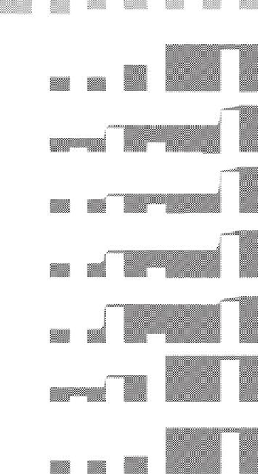
FIGURE 5.47
Operational diagram of one pixel in a 4-Tr configuration: (a) cross-sectional view; (b) operational diagram by
potential distribution.
of metal wiring is necessary with the
n
-type region of the PD in a 4-Tr pixel, it is pos-
sible to cover the
n
-type region with a
p
+
layer to form a buried PD to suppress dark
current drastically. As capacitance of FD can be designed without reference to PD per-
formance, it is possible to realize a higher charge-voltage conversion factor, which is
inversely proportional to
C
in
. These are huge advantages of 4-Tr pixel over 3-Tr pixel
CMOS sensors. Therefore, CMOS sensors aiming for high performance employ a 4-Tr
pixel configuration.
The noises in 4-Tr pixel configuration are reset noise of FD, FPN caused by variation of
threshold voltage, 1/f noise, and thermal noise of the drive transistor in SFA. Among these,
reset noise of FD, FPN due to
V
th
variation, and part of 1/f noise of the drive transistor can
be removed by a cancellation operation by CDS. The high-frequency component of ther-
mal noise is removed due to the narrow bandwidth of CDS.


