Hardware Reference
In-Depth Information
Table 3-3.
Nunchuk Connector Wiring
Pin
Wii Wire
CloneWire
†
Description
P1
Gnd
White
White
Ground
P1-25
SDA
Green
Blue
Data
P1-03
+3.3 V
Red
Red
Power
P1-01
SCL
Yellow
Green
Clock
P1-05
†
Clone wire colors vary!
Before you cut that connector off your clone, consider that you'll need to trace the
connector to a wire color. Cut the cable, leaving about 3 inches of wire for the connector.
Then you can cut the insulation off and trace the pins to a wire by using an ohmmeter
(or by looking inside the cable-end connector).
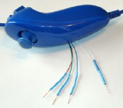
Figure
3-1
shows the author's clone Nunchuk with the connector cut off. In place
of the connector, solid wire ends were soldered on and a piece of heat shrink applied
over the solder joint. The solid wire ends are perfect for plugging into a prototyping
breadboard.
Figure 3-1.
Nunchuk with wire ends
Testing the Connection
Once you've hooked up the Nunchuk to the Raspberry Pi, you'll want to perform some
simple tests to make sure it is working. The first step is to make sure your I2C drivers are
loaded:
$ lsmod | grep i2c
i2c_bcm2708 3759 0
i2c_dev 5620 0