Hardware Reference
In-Depth Information
Reset Timing
The only parameter of interest for timing apart fr
om the
I2C bus is the device reset time.
In order for the device to see a reset request, pin
RESET
must remain active (low) for a
minimum of 1 μs. The device resets and places outputs into the high-impedance mode
within a maximum of 1 μs.
Circuit
Figure
2-2
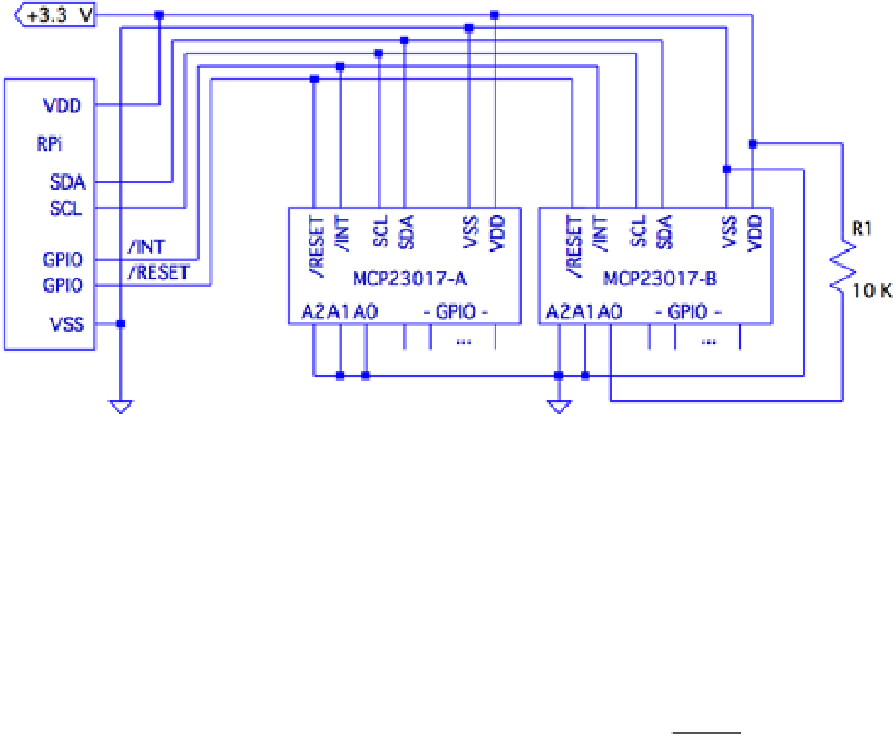
shows a circuit with two remote MCP23017 GPIO extenders c
onnec
ted
to on
e I2C bus. In the figure, the power, ground, I2C data, and optional
RESET
and
INT
connections are shown connected through a six-conductor ribbon cable. This
allows the Raspberry Pi to communicate remotely to peripherals in a robot, for example.
Figure 2-2.
MCP23017 circuit
The data communication occurs over the pair of signals SDA and SCL. These are
connected to the Raspberry Pi's pins P1-03 and P1-05, respectively (GPIO 2 and 3 for Rev
2.0+). The other end of the I2C data bus is common to all slave peripherals.
Each MCP23017 slave device is addressed by its individually configured A2, A1,
and A0 pins. For device A, these pins are shown grounded to define it as device number
0x20
(low bits are zeroed). A1 is tied high for device B so that its peripheral address
becomes
0x21
. In this configuration, the Raspberry Pi will use addresses
0x20
and
0x21
to
communicate with
these s
lave
devic
es.
Lines labeled
RESET
and
INT
are optional connections. The
RESET
line can be
eliminated if you never plan to force a hardware reset of the
slav
es (tie to
V
DD
through a
10 K resistor). Usually the power-on reset is sufficient. The
INT
line is more desirable,
since the MCP23017 can be programmed to indicate interrupts
whe
n a GPIO input has
changed in value (or does not match a comparison value). The
INT
line is an open
collector pin so that many can be tied together on the same line. However, the Pi will have