Hardware Reference
In-Depth Information
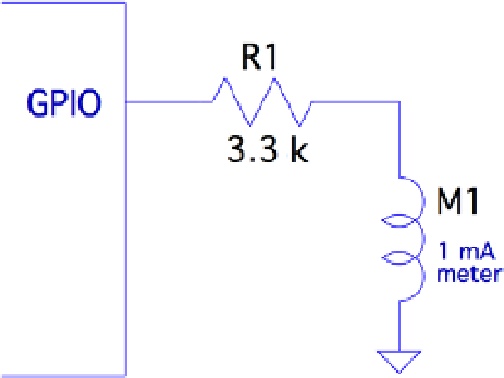
Meter Circuit
Figure
9-1
shows the circuit used for this chapter's CPU percent meter. The resistor
R1 = 3.3 kW when you use a 1 mA meter movement.
Figure 9-1.
PWM-driven meter
If you know the current-handling capability for the meter you would like to use, you
can calculate the resistance needed as follows:
V
1
=
I
m
R
where:
•
V
is the voltage (3.3 V) at the GPIO pin.
•
I
m
is the current for your meter movement.
If your meter is known to use a 100 mA movement, for example, the series-dropping
resistor would work out to be the following:
33
0 0001
33
.
R
=
1
.
=
K
W
For all projects in this topic, I encourage you to substitute and try parts that you
have on hand. You may have a junk-box meter somewhere that you can use. Don't
use automotive ammeters, since they will usually have a shunt installed. Almost any
voltmeter or meter with a sufficiently sensitive movement can be used. The limit is
imposed by the GPIO output pin, which supports up to 8 mA (unless reconfigured).
If you don't know its movement sensitivity, start with high resistances and work
down (try lowest currents first). With care, you can sort this out without wrapping the
needle around the pin.