Hardware Reference
In-Depth Information
Figure
6-9
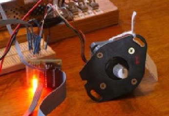
shows how a pointer knob can be used for a pointer. Otherwise, this is
your opportunity to get creative.
Figure 6-9.
Stepper motor with knob used as a pointer
At power-on reset and boot time, the selected GPIO lines are all input pins with pull-
down resistors. After boot-up, when the program starts and configures its GPIO pins, it
will do the following:
1.
Configure an output low value for each GPIO (while still an input)
2.
Configure the GPIO pin as an output
Step 1 eliminates the possibility of a stepper winding being driven before the
software is ready to drive it. If this were not done, a driver could be activated when
the GPIO is first configured as an output. Step 2, of course, is necessary to drive the
ULN2003A chip. But no glitch occurs in the output when step 1 is performed first.
After the main program has begun, it saves the current terminal settings in
sv_ios
and then sets up a raw mode, permitting single-character I/O interaction (lines 167-173).
See Chapter 9 of
Raspberry Pi Hardware Reference
(Apress, 2014) for more information
about the serial API.
Lines 175-178 initialize the GPIO lines to drive the stepper-motor field windings.
The default stepper-motor mode is configured on line 182, which may be overruled by
a command-line argument. The program can also change modes by using keystroke
commands.
The remainder of the program is a
while
loop that extends from lines 185-241. It
reads a single-character command at line 187 and then dispatches to sections of code in
the
switch
statement. The single-character commands are summarized in Table
6-3
.