Environmental Engineering Reference
In-Depth Information
Read input files
(constant parameters, sediment, dimension,
control structures, lateral flows and base flows)
read hydraulic and
morphological data
of previous time step
c
ompute discharges
at each subsection
irrigation schedules
Hydraulic calculations
critical depth subroutine
compute normal and
critical water depths
compute water depths at
control points (subroutine
for control structures)
normal depth subroutine
compute actual
water depths
subroutine for gradually
varied flow profile
(predictor corrector)
equivalent roughness
(bed forms, maintenance)
store hydraulic
results
equivalent roughness
(bed forms, maintenance)
Morphological calculations
compute equilibrium
concentration
(subroutines for predictors)
compute sediment
concentration
subroutine for the solution
of mass balance equation
compute morphological
changes
correction for non-wide
canal condition
compute new bed level,
width and slope
subroutine for non-
equilibrium concentration
store morphological
results
repeat until the end
of simulation period
next time step
end
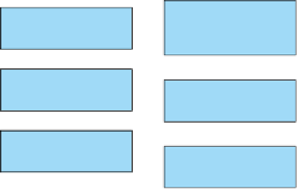
Figure 6.1. Flow diagram of SETRIC for calculating the water flow, sediment transport and changes in bottom level in main
and/or lateral canals (after Paudel, 2002).


Search WWH ::

Custom Search