Environmental Engineering Reference
In-Depth Information
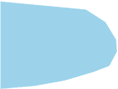
FIGURE 20.10
Illustration of Silt Fence Installed
along the Contour
Install silt fence
along the contour
Direction
of flow
●
Silt fence should be installed along
the contour (on a level horizontal
plane)
●
Turn up the ends (J-hooks) to help
pond the water behind the fi lter
●
Ensure that the fi lter is trenched
in with the stakes on the downhill
side (trench should be 15 cm deep
by 15 cm wide).
●
Remove sediment when it reaches
1/3 the height of the barrier
●
Filters should not be installed
where concentrated fl ow is
expected
as mentioned in an earlier section, a silt fence or sediment i lter is less effective if there are
well-dei ned channels coming from the disturbed land. Concentrated water l ow requires
other measures.
The basic principle in designing control measures for concentrated water l ow leaving
disturbed land is to ensure that the viability of ecosystems, aesthetic values and down-slope
areas are not signii cantly adversely affected. Managed water, whether diverted or leav-
ing the site, usually has an increased l ow rate and sediment load. Poorly designed exits
from disturbed land can result in off-site erosion near discharge points. Water and sedi-
ment retention basins, sediment traps and constructed wetlands are common erosion con-
trol techniques for managing this problem.
Sediment retention basins are impoundments designed to intercept sediment-laden run-
off and to retain a signii cant portion of the sediment. Their design and operation depend
primarily on the nature of eroded materials and thus must be site-specii c. Coarse-grained
sediment settles faster than i ne-grained sediments. Clay particles may form a colloid that
settles in a more loosely packed structure, taking up more volume, reducing the effective-
ness of the settling pond.
Three design criteria are used in sizing the settling zone of a sediment basin, namely
'surface area' (dei ned as design volumetric l ow rate divided by the settling velocity of the
design particle), depth and the ratio of length to width. The i nal basin design must allow for
sediment storage for either the entire duration of soil loss or until the basin is cleaned out.
Sediment retention basins also attenuate runoff, regulating water l ow leaving dis-
turbed land and hence, reducing l ow velocities and stream-channel erosion downstream.
In effect, they act as run-on controls for the next area down-slope.
An integrated part of water and sediment retention basin design and function is the
design of water discharge points. Care must be taken to ensure that the energy gen-
erated by the outl ow is safely dissipated. Techniques for energy dissipation vary with the
anticipated l ow rates. They range from a relatively simple protective rip rap lining of
the stream-channel close to the outlet to permanent structures comprising heavy gabions
(baskets of rocks), stones or concrete structures (
Figure 20.11
)
. Another technique to dissi-
pate energy is to direct the discharge into a suitably large body of water that has the capa-
city to absorb the discharge without damage.
Managed water, whether
diverted or leaving the site,
usually has an increased fl ow rate
and sediment load.
An integrated part of water and
sediment retention basin design
and function is the design of
water discharge points.


Search WWH ::

Custom Search