Environmental Engineering Reference
In-Depth Information
Profile of Waste Rock Formed by
Top Down Construction
Crest
Over-Steepened (unstable) Slope
Angle of Repose (meta-stable) Slope
37.38
°
Original Ground Surface
Rill Slope-
Larger Boulders
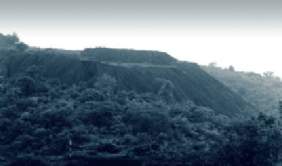
Waste Rock Dump by Top-down Dumping, Chhattisgarh, India
Profile of Waste Rock Formed by
Bottom Up Construction
Crest
13
12
11
Excavated
Drainage
Channel
10
9
8
Original Surface
7
6
5
4
To e
Paddock Dumping of Waste Rock. Three Layers are Visible - Lowest Layer at Left
FIGURE 19.4
Profi le of Waste Rock Storage
Formed by Top Down and Bottom Up
Construction
Marine disposal of waste rock was used at the Misima Gold Project in PNG, and is cur-
rently used at the Lihir Gold Project (also in PNG). In both cases, the reasons for adopt-
ing marine disposal were the lack of land suitable for onshore disposal and the predicted
low impacts of marine disposal. While both cases of marine disposal have been widely
criticized by environmental NGOs, monitoring has confirmed that impacts on the marine
environment have been relatively minor, temporary, and in accordance with predictions
made in the relevant EIAs.
While both cases of marine
disposal have been widely
criticized by environmental
NGOs, monitoring has
confi rmed that impacts on the
marine environment have been
relatively minor, temporary, and
in accordance with predictions
made in the relevant EIAs.
19.5 ALTERNATIVE DESIGN AND CONSTRUCTION
APPROACHES
There are two main approaches to construction of waste rock storages:
●
Top-down dumps, in which the waste rock is dumped over an advancing face, known as
the angle of repose, sloping at approximately 38º from the horizontal, as shown in profile
on the upper part of
Figure 19.4
. After dumping is complete, the dump is re-shaped to
its intended configuration, usually using bulldozers. In many older mining operations,
no re-shaping was carried out, the angle of repose slope being the final outslope.
●
Bottom-up storages in which the waste rock is dumped in a series of piles, and then spread to
form a relatively thin layer. This is sometimes referred to as paddock dumping (
Figure 19.4
).
Subsequently, the process is repeated until the ultimate storage configuration is achieved.
Hybrid or intermediate approaches are also used, whereby top-down dumping is used
to produce relatively thick, (e.g. 10 m or 15 m) layers, which are then overlain by subse-
quent equally thick layers. This approach is safer and requires less re-shaping than the full
height top-down approach.
The advantages and disadvantages of top down versus bottom up construction are com-
pared in
Table 19.1
.


Search WWH ::

Custom Search