Graphics Programs Reference
In-Depth Information
•
The details of the configuration of vertical
panels and components of the window and
the door.
the case selected for representation in the virtual
environment. In cross-section, the deck of the
viaduct shows a box girder solution and its height
varies in a parabolic way along its three spans.
The most common construction technique for this
typology is the cantilever method of deck bridge
construction.
A computer graphic system which enables
the geometric modeling of a bridge deck of box
girder typology was used to generate, 3D models
of deck segments necessary for the visual simula-
tion of the construction of the bridge. Geometric
description can be entered directly into the deck-
modeling computer product. To achieve this, the
developed interface presents diagrams linked to
parameters of the dimensions, so facilitating the
description of the geometry established for each
concrete case of the deck. Figure 10 shows the
interface corresponding to the cross-section of the
deck and the 3D model of a bridge deck segment.
To complete the model of the bridge, the pillars
and abutments were modeled using the
AutoCAD
system. Then followed the modeling of the ad-
vanced equipment, which is composed not only
of the form traveler, but also the formwork adapt-
able to the size of each segment, the work platforms
for each formwork and the rails along which the
Through direct interaction with the model, it
is possible both to monitor the progress of the
construction process of the wall and to access
information relating to each element, namely, its
composition and the phase of execution or as-
sembly of the actual work, and compare it with
the planned schedule. This model had been used
to distinct advantage as an educational aid in Civil
Engineering degree course modules.
VR model of the Cantilever
method of Bridge Construction
The second model created allows the visual
simulation of the construction of a bridge us-
ing the cantilever method. Students are able to
interact with the model dictating the speed of the
process, which allows them to observe details
of the advanced equipment and of the elements
of the bridge (pillars, deck and abutments). The
sequence is defined according to the norms of
planning in this type of work. The North Viaduct
of the Bridge Farm, in Madeira, Portugal, was
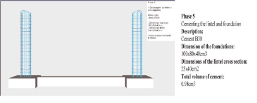
Figure 9. Presentation of text describing the exhibited phase
Search WWH ::

Custom Search