Environmental Engineering Reference
In-Depth Information
Well
pumping rate Q
Earth Surface
Aquitard
H
Groundwater
Flow
Aquifer
transmissivity T
Aquitard
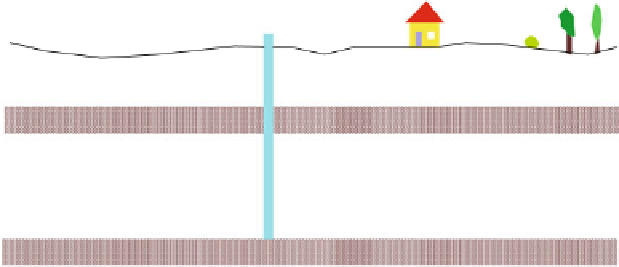
Fig. 12.1
Schematic cross-sectional view of a well pumping from a confined aquifer
radially towards an installed pumping well. It is assumed that the situation is totally
equal in all radial directions, which allows the use of the radius
r
as the space
variable. It is also assumed that there are no differences in vertical direction: the
well is screened across the entire aquifer and there are no differences concerning the
hydraulic properties within the permeable layer. The aquifer remains water
saturated, i.e. there are no parts that fall dry due to pumping.
In the idealized situation shown in Fig.
12.1
, the aquifer is characterized by
a thickness
H
[m] and a transmissivity
T
[m
2
/s]. In the transmissivity parameter
the hydraulic conductivity
K
of the porous material and the thickness of the aquifer
H
are represented:
T ¼ K H
(12.1)
T
increases with thickness;
T
is higher for more permeable aquifers. It is assumed
that the well withdraws water at a constant rate
Q
[m
3
/s], which allows the
description of the steady state groundwater flow. The relevant variable for the
analysis of groundwater flow is the piezometric head
h
, which changes with
the distance
r
from the well position. Piezometric head is the key variable for
flow (see Darcy's Law, Chap. 11), quantifying the height of the water table above
some reference level measured by a piezometer. A piezometer is a pipe that is open
at both ends, and reaches into the aquifer with the lower end).
h
decreases if the well
is approached and can be calculated by using the formula of Thiem (
1906
):
Q
r
r
0
hðrÞ¼h
0
þ
log
(12.2)
pT
2
with:
h
0
piezometric head above base at radius
r
0
[m]
Q
pumping rate [m
3
/s]
T
transmissivity of the aquifer [m
2
/s]
r
0
radius [m]