Environmental Engineering Reference
In-Depth Information
A slurry bubble column is a large vessel filled with liquid (the products) in which
the catalyst particles are suspended. These particles are small (
m) such that no
internal diffusion limitations occur. The syngas feed enters at the bottom, while the
liquid products are removed from the upper part of the reactor. The technical challenge
is to effectively separate the small catalyst particles from the product fluid, after which
the catalyst can be recycled. Syngas is distributed at the bottom of the column and rises
as bubbles through the liquid in upward direction. The reactants from the bubbles (H
2
and CO) dissolve in the liquid and react at the catalyst surface. Slurry bubble columns
are typically operated at high gas fractions and high catalyst loadings, both around
30 vol.%. At such high gas fractions, the bubbles typically have a bimodal distribu-
tion: small ones of a few millimeters and large ones of a few centimeters in diameter.
Especially the large bubbles lead to a vigorous mixing of the slurry, preventing set-
tling of the solids and giving a rather even temperature distribution in the reactor.
Because of the large heat production by FTS, the reactor contains a large number
of heat exchanging tubes. The removed heat is not lost: it is used to generate steam.
The conversion in a slurry bubble column is typically rather high, up to 80
50
μ
90%.
A packed bed is an amount of particles packed together, in the case of an FT reactor
enclosed by a vertical tube. The outer side of the tube is cooled by boiling water. The
catalyst particles are porous themselves, but in the packed bed, there is also porosity
(
−
40 vol.%) between the particles. Typically, a part of the product stream leaving the
reactor is recycled to have liquid present right from the entrance of the reactor. This is
done to ensure sufficient heat transfer from the particles to the cooled tube wall. To pre-
vent too high a pressure drop, the catalyst particles cannot be too small; typically, par-
ticles of a fewmillimeters in diameter are used. Adrawback of this relatively large size is
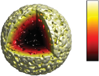
that diffusion limitations inside the particle will occur, so that the central part of the par-
ticle is not used as optimal as the outer region due to lower concentrations of the reactants
(seeFigure 17.5). Another challenge is the removal of heat: the heat transport in the radial
direction is poor. Therefore, packed beds for FTS have a maximum diameter of just few
centimeters. In order to reach reasonable production rates, ten thousands of tubes con-
taining the catalyst particles are put in parallel and placed in a vessel containing boiling
1
0
Dimensionless
CO concentration
FIGURE 17.5
Typical dimensionless CO concentration in an FT catalyst particle of 1.5 mm
in diameter (based on Vervloet et al. (2012)).


Search WWH ::

Custom Search