Environmental Engineering Reference
In-Depth Information
nrel.gov/rredc/. Fluctuations of over 10% in solar supply are possible between the
individual years given.
10
°
W
5
°
W
0
°
5
°
E
10
°
E
15
°
E
20
°
E
25
°
E
2
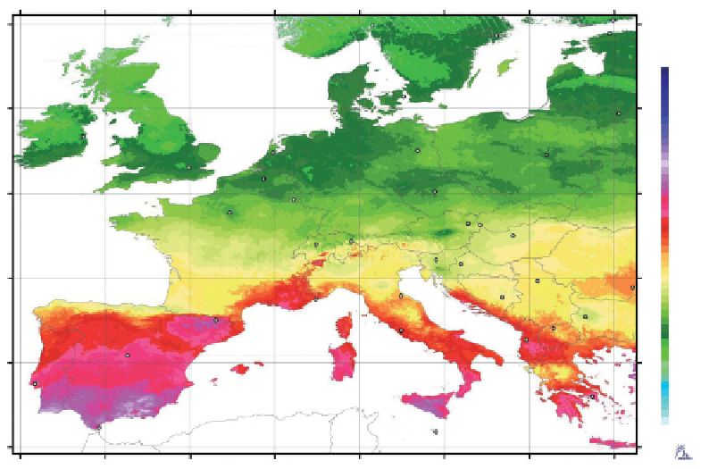
kWh/m
> 2420
2381−2420
2341−2380
2301−2340
2261−2300
2221−2260
2181−2220
2141−2180
2101−2140
2061−2100
2021−2060
1981−2020
1941−1980
1901−1940
1861−1900
1821−1860
1781−1820
1741−1780
1701−1740
1661−1700
1621−1660
1581−1620
1541−1580
1501−1540
1461−1500
1421−1460
1381−1420
1341−1380
1301−1340
1261−1300
1221−1260
1181−1220
1141−1180
1101−1140
1061−1100
1021−1060
981−1020
941−980
901−940
861−900
821−860
781−820
741−780
701−740
661−700
621−660
581−620
541−580
501−540
<501
10
°
W
5
°
W
0
°
5
°
E
10
°
E
15
°
E
20
°
E
25
°
E
Figure 5.15
Average yearly totals for solar radiation energy in Europe.
Source: Meteonorm, www.
meteonorm.com.
However, the values only apply to the horizontal orientation of a system. If a system
is mounted on a sloping roof, the roof determines the orientation of the system. In
an optimal case, the roof would be tilted about 30° to the south in Europe and North
America. With an optimal orientation towards the sun the supply of solar radiation
increases by around 10%. However, good radiation values are still achievable even
if the orientation is less favourable. Figure 5.16 shows the tilt gains and losses for
all possible orientations for Berlin. These values can also be applied to other loca-
tions in Central Europe.
If a photovoltaic system is to be installed on a roof or in a green fi eld, the photo-
voltaic modules can be orientated optimally 30° towards the south. If the solar
modules are set up in several rows one behind the other, they will create shade for
one another as the sun goes down. As a result, a distance at least twice the module
height should be maintained between the rows of modules. In this case, however,
only one-third of the area is useable. The loss due to shade then usually amounts to
less than 5%.