Graphics Reference
In-Depth Information
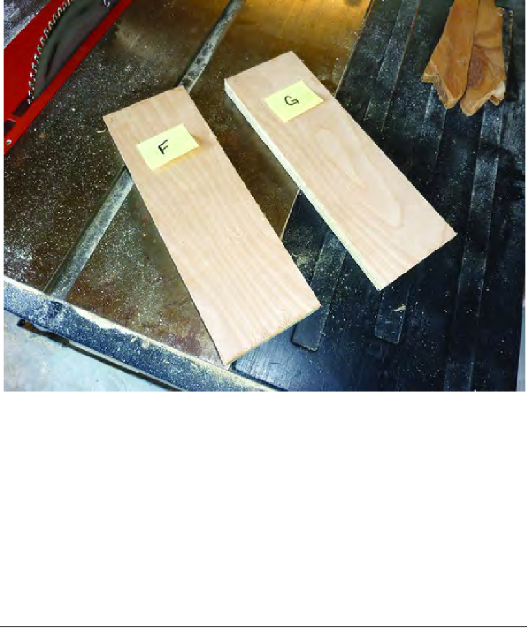
Figure 4-10. Part F and G are ready for additional cuts and drilling.
Figure 4-11 shows the Upper Structural Sides (shaded) attached to Parts A and B. Additional holes
in this piece will allow you to increase or decrease the height of the 3D printer, which in turn affects the
maximum height of a printable object.
■
Note
You may be wondering why this raising and lowering feature is available. The high position has the least
amount of rigidity but has more clearance for tall 3D print jobs. The low frame position adds a great amount of
rigidity for machining operations but has the least amount of clearance, which is appropriate since machining is
generally done on low-profile parts. The builder can, for example, consider a high frame setting for foam
machining since there will be very little load on the cutter. Ultimately, you'll need to experiment and adjust
your 3D printer based on the printing or milling job (using a small router or Dremel device) at hand.

Search WWH ::

Custom Search