Graphics Reference
In-Depth Information
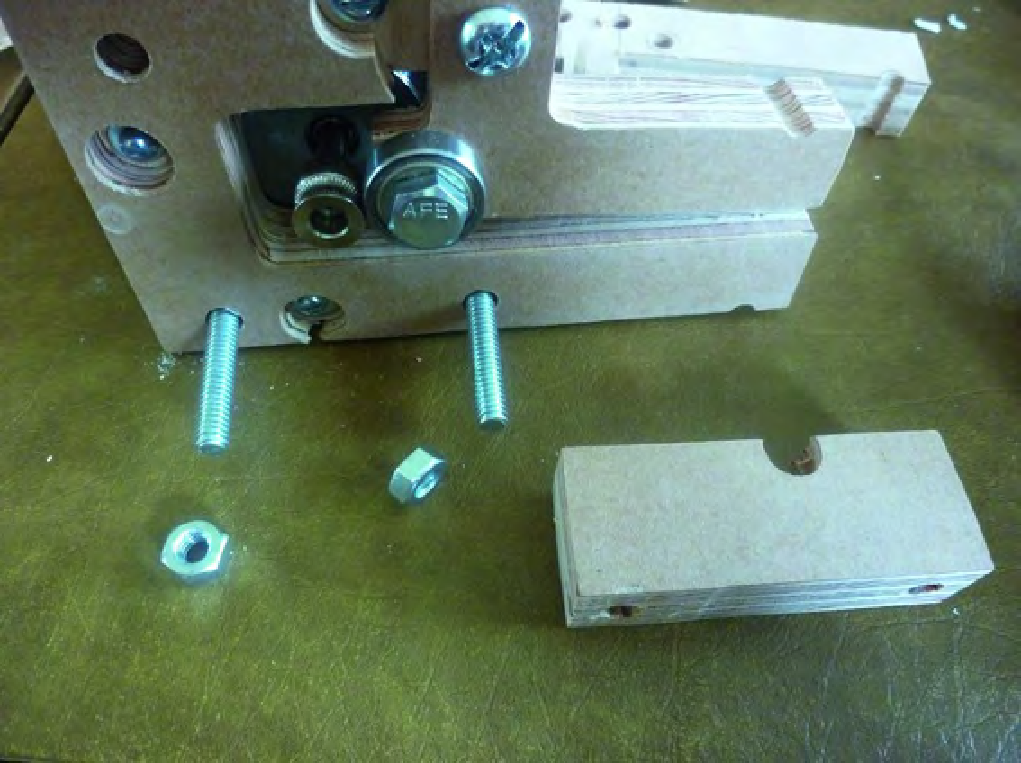
Figure 21-9. Part S will be temporarily bolted on to Part Q.
Insert two 2-1/2" machine screws through Part Q, as shown in Figure 21-9. Add Part S so that the
hole is up against Part Q and secure with two ¼" nuts, as shown in Figure 21-10.
Search WWH ::

Custom Search