Graphics Reference
In-Depth Information
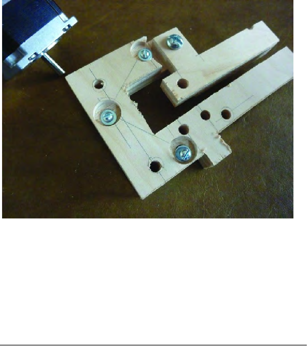
Figure 15-5. The stepper motor is bolted to Part Q with three #6-32 machine screws.
Place the motor so that the wires on the motor are facing away from Part P (the smallest of the two
wood parts) and secure the motor with the three nuts. Figure 15-6 shows the motor added to Part Q and
secured with three #6-32 nuts.
■
Note
It helps to hold a nut in place over the holes on the stepper motor as you screw in the machine screws.
The nuts can't rotate due to the small edges on the motor, so just hold them with your finger as you tighten the
screws. Tighten the screws a little at a time; the motor has a tiny protruding circular surface around the motor
shaft that will prevent the motor from bolting to Part Q flush. The motor will be slightly raised from Part Q (about
the thickness of a washer); this is normal.

Search WWH ::

Custom Search