Graphics Reference
In-Depth Information
•
Qty-1 heat sink for feed cylinder on extruder
•
Qty-1 NEMA 23 Stepper Motor
Attach Extruder Bearing Hinges I and II
The Extruder will be bolted to a mechanism that consists of Parts P and Q, the Extruder Bearing Hinges I
and II.
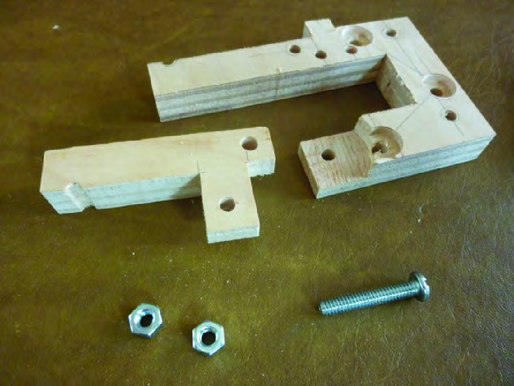
Figure 15-1 shows Parts P and Q along with the single 1/4” x 1-1/2” bolt and two nuts that will
connect the two parts together.
Figure 15-1. Parts P and Q will be bolted together.
Insert the 1-1/2” machine screw through Part P and into Part Q, as shown in Figure 15-2.
Search WWH ::

Custom Search