Graphics Reference
In-Depth Information
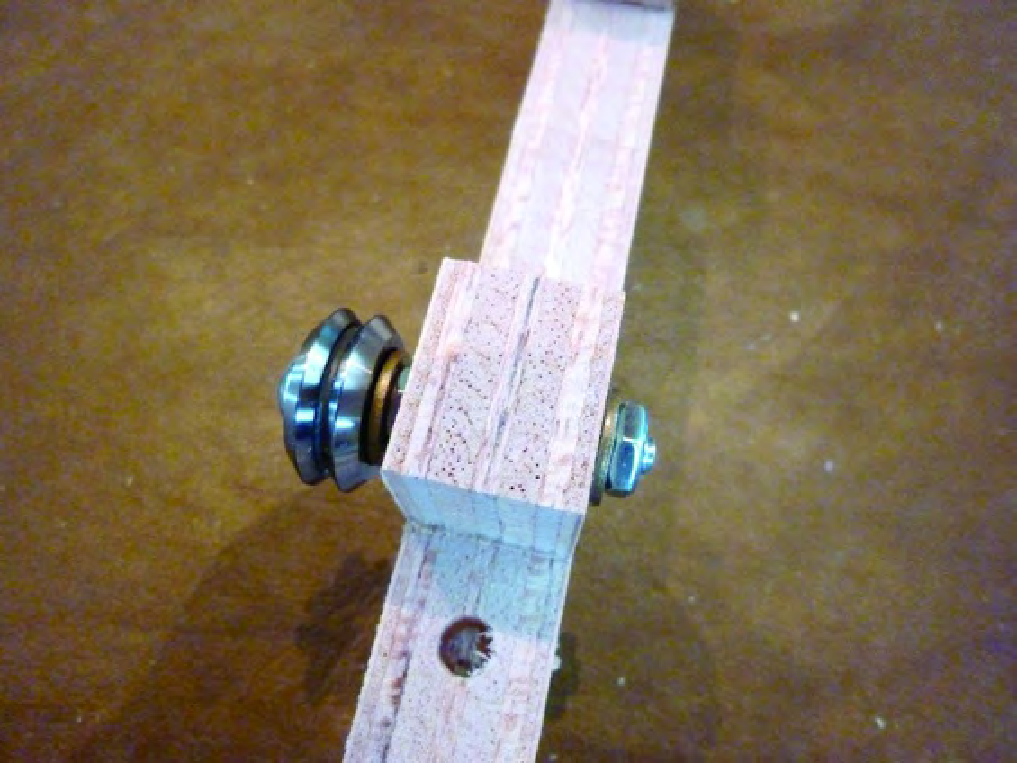
Figure 12-10. Secure the v-groove bearing with a washer and nut.
Perform the previous actions for the remaining hole on Part I and the two smaller holes of Part J.
Figure 12-11 shows Parts I and J with the v-groove bearing assemblies added.
Search WWH ::

Custom Search