Graphics Reference
In-Depth Information
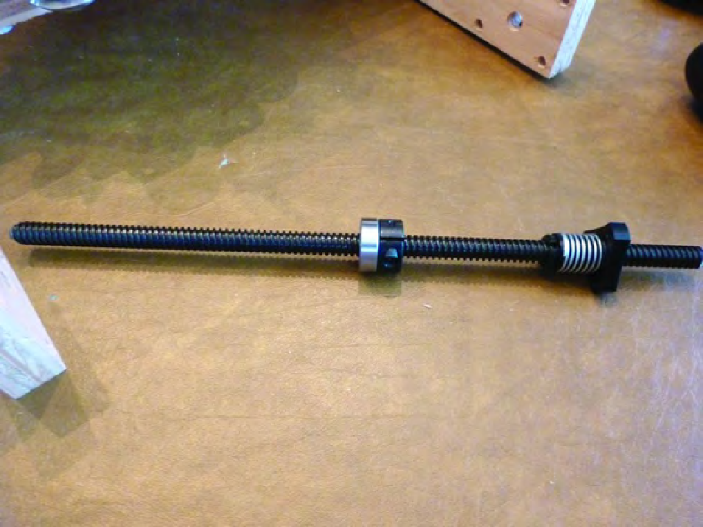
Figure 12-2. A collar and a bearing inserted onto the lead screw
Insert the lead screw end closest to the bearing (hold the collar and bearing so they don't slide off)
through the counterbored hole on the Z-Axis Bearing Support (Part L). The other end of the lead screw
(with the ABN) will be inserted through the large center hole of Part N (Z-Axis Nut Mount). Next, use
three #6 machine screws (1-1/4” length) inserted through the three holes surrounding the lead screw in
the ABN and insert these into the holes of Part N, as shown in Figure 12-3.
Search WWH ::

Custom Search