Graphics Reference
In-Depth Information
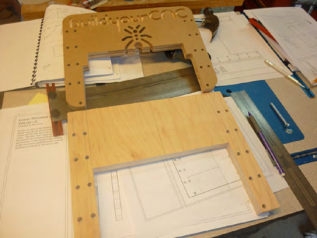
Figure 7-13. A Part O cut by us and and one by Patrick's CNC machine.
Lower Structural Side - Part A and B
There are two Lower Structural Sides that we've labeled Parts A and B. You can use the building plans to
measure and mark the locations of all the holes to be drilled as well as the extra material that must be cut
away, but we'd like to walk you through another method that we used for these two parts.
First, these two parts are mirror images, and neither part has any counterbore holes that must
be drilled. This means that we can put Part A on top of Part B and drill and cut through both parts at
the same time. This will ensure that all holes and cuts match up—and it will save us time. Here's how
we did it.
First, we cut out the actual-size template from the building plans. Note that this will only work if you
print out the building plans on 11x17 paper with no reduction! You can use a ruler to measure the
actual-size template against the building plan sheet that has the measurements on it. If the actual-size
template matches, you're in good shape. Figure 7-14 show the actual-size template being cut out.
Search WWH ::

Custom Search