Information Technology Reference
In-Depth Information
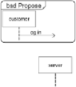
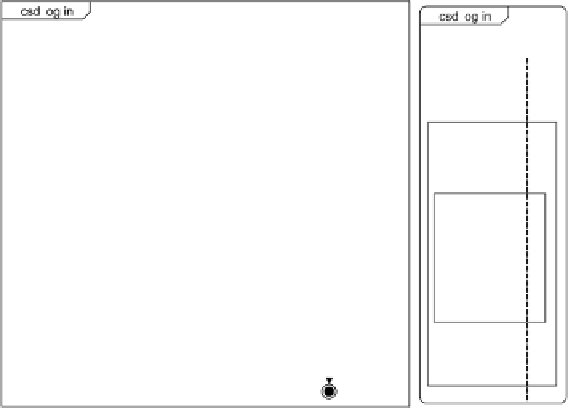
Fig. 1.
Examples of bSDs and combined SD
Fig. 2.
Example of a bSD
generates two traces:
{<e
1
,e
3
,e
2
,e
4
>
;
<e
1
,e
2
,e
3
,e
4
>}
. These traces imply
that the events
e
3
are not ordered. For this reason, we use the notion of
partial order as used in other languages of scenarios as Message Sequence Charts
to define formally the notion of bSD:
e
2
and
Definition 1.
A basic sequence diagram is a tuple
B
I,E,≤,A,α,φ,≺
=(
)
where:
I
is a set of objects participating to the interaction,
E
is a finite set
of events (message emissions and receptions),
≤
is a partial ordering imposed by
lifelines and messages,
are
mappings associating respectively an action name and a location (i.e. an object
affected by the event) with an event.
A
is a set of actions (message name), and
α
and
φ
≺⊆ E × E
is a relation that pairs message
emissions and receptions.
In Definition 1, the sentence “
is a partial ordering imposed by lifelines and
messages” means that events are totally ordered along a same lifeline (for in-
stance, in Fig. 2 the event
≤
e
1
precedes the event
e
2
,andtheevent
e
3
precedes
the event
e
4
), and a message emission must always precede the corresponding


Search WWH ::

Custom Search