Environmental Engineering Reference
In-Depth Information
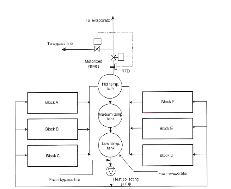
Figure 5. Collector bank consisting of six blocks A, B, C, D, E and F.
76 array pairs are arranged in a U-shape to form the whole collector bank. All array pairs
are connected in parallel and each is provided with two isolating valves- at inlet and exit-, a
drain valve, and an air vent. The bank is divided into six blocks designated A, B, C, D, E and
F. Blocks A and F consists of 12 array pairs while the other blocks each consists of 13 array
pairs. Figure 5 is a block diagram of the collector field.
3.1.2. The Heat Accumulator Subsystem
The heat accumulator subsystem (see figure 6) is designed to provide thermal energy to
the evaporator during its 24 hours per day operation. It consists of three carbon steel tanks
having a total capacity of 300 m
3
and contains hot water at a temperature ranging from 74
o
C
to 99
o
C and at atmospheric pressure. The tanks are insulated with a 100 mm layer of
fiberglass to minimize heat loss to the ambient air. All three cylindrical tanks have the same
internal diameter (3.8m) and wall thickness (9mm). However, the tank heights are not
identical with tank No. 1 having an effective height of 10m while tanks No. 2 and 3 having an
Search WWH ::

Custom Search