Graphics Programs Reference
In-Depth Information
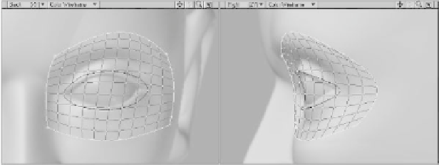
We've now got two sets of splines radiat-
ing out from the eye of our model. The area
enclosed by these splines forms a loop,
known as an
edge loop
. When we patch the
splines in this loop, the resulting polys will
follow the basic musculature of the
orbicularis oculi shown as the dark polys in
Figure 14-15.
to ensure that the points in your splines are
merged together properly. Figure 14-16
shows the results.
Wait a minute. This is just a grid-like
mesh. We were expecting a nice clean edge
loop. What happened? Well, here's the prob-
lem. Even though we built our splines with
four sides (as described in Tip #2), the
outer
splines have no way of knowing that
they should be bounded by the
inner
splines. When we patched the outer splines,
they generated polys that ran right over the
inner splines. That's
definitely
not what we
want. In order to resolve this, we need to
link the outside splines to the inside splines
so that we can patch the region
between
them.
Go ahead and undo the spline patch.
9.
Add three points in a roughly horizontal
line about the center of the eye. They
should mimic the points in the splines
above and below them. In other words,
the middle point should stick out far-
ther than the ones on the left and right.
Deselect these, then select the points
shown in Figure 14-17 and create a
new spline.
Figure 14-15: The orbicularis oculi edge loop.
Let's go ahead and patch them now. Select
the splines of the outer loop in a counter-
clockwise fashion and press <
Ctrl
>+
<
f
>. Accept the defaults of
10
Parallel and
10
Perpendicular and press
OK
. If you get a
“Curves Do Not Cross” error, press <
m
>
Figure 14-16: The results of patching the outside splines.