Graphics Programs Reference
In-Depth Information
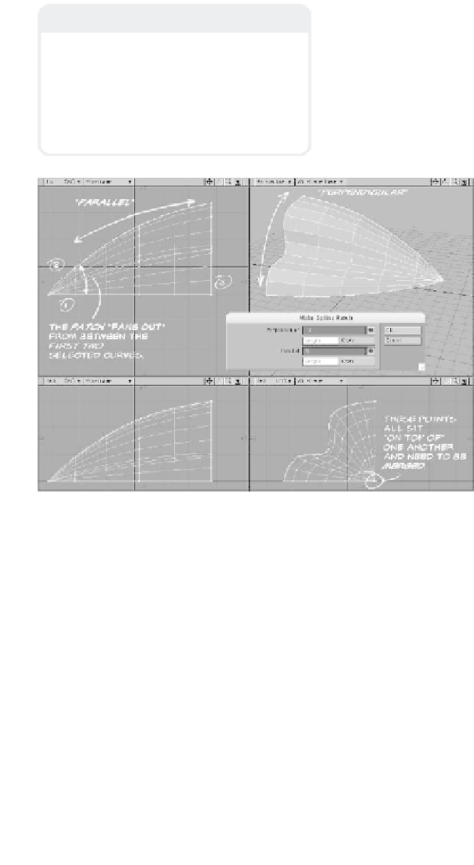
Note
When patching areas that are defined by
three curves, Modeler “fans out” its geome-
try from the point where the first two curves
selected meet. (So, by selecting your curves
in a different order, you can be presented
with completely different patch shapes —
see Figures 12-2 through 12-4.)
Figure 12-2
•
Length
specifies that the entered
number of polygonal rows are to be evenly
spaced along the length of the curves that
define it.
•
Knots
specifies that the entered num-
ber of polygonal rows be weighted relative
to the points that hold the shape of the
curves. (More knots means more polys;
this is a way of letting areas of more detail
get more of the rows than other areas.)
Selecting the curves in the order shown in
Figure 12-1 and then using
Construct |
Patches | Patch
(or the <
Ctrl
>+<
f
>
keyboard shortcut) brings up a window
where you control aspects of the patch to be
created.
•
Perpendicular
refers to the number of
polygonal rows that will be created, like the
“ribs” of a fan, radiating out from the point
where the first two selected curves join.
•
Parallel
refers to the rows of polys
that stretch between the first two selected
curves.