Graphics Programs Reference
In-Depth Information
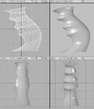
Figure 5-29
2.
Next, with the curves in a
background
layer
, create a shape you wish to be
extruded. In this case, it is a standard
disc that is wider in X than it is in Z.
Position it at the curves' start points
with its normal facing
out
.
Note
Using the Knots setting to determine seg-
ment placement means you must be a lot
more careful when creating the curves you
will be “lofting” along. LightWave will try to
distribute
segments
and
orient
them knot for
knot. If your object's silhouette must meet
an exact shape, have all your curves made
with the same number of knots, and know
that from the first knot to the last on all
curves, LightWave will use them to deter-
mine exact placement and angle of the
extruded segments.
3.
Activate Rail Extrude to bring up the
Rail Extrude: Multiple window. It has
the following options:
•
The
Segments
section allows you
to control how “dense” the extruded
mesh is (just like Rail Extrude with
only
one
curve in the background).
•
Strength
is a factor of how
“tightly” the extrusion will follow the
curves.
•
Oriented
, as when rail extruding
with only
one
curve, “angles” the
extrusion as it follows the curves.
•
Scaling
lets your extrusion
“expand” on all three axes in relation to
the distance between the two curves.
Figure 5-30: Using just the default settings for Rail
Extrude: Multiple (shown in Figure 5-29), we get
our funky handgrip.