Environmental Engineering Reference
In-Depth Information
cells. In the double cell configuration, 5% potassium for-
mate solution was placed in the center, anode and cathode
liquid chambers whereby the potassium and the formic acid
components were expected to filter through the soil into the
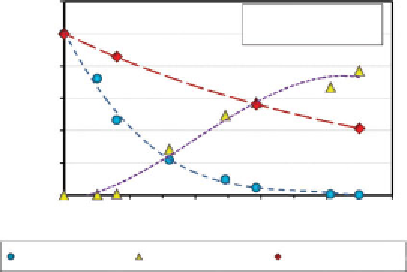
oppositely charged electrode chambers. In the single cell
configuration, 5% potassium formate solution was placed
only in the anode electrode chamber and potassium was
expected to filter through the soil into the cathode electrode
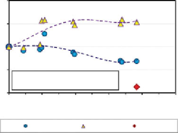
chamber. The results of these tests are presented in figures
2.31 and 2.32. In both tests, the potassium concentration
increased at the cathode and decreased in the anode and the
2.0
1.5
1.0
0.5
Electric Potential = 100V
Soil Type II: bentonite, kaolinite, silt, fine
and medium sand; 20 % each by mass
0.0
0
50
100
Duration of treatment, hrs
150
200
250
Center cell
Cathode
Anode
Figure 2.31
Evolution of potassium and concentrations in the electrode sites and center
in double cell EK test
1.2
Electric Potential - 45V
Soil Type I: 20% bentonite,
80% kaolinite by mass
1.0
0.8
0.6
0.4
0.2
0.0
0
50
100
Duration of treatment, hrs
150
200
250
Potassium in Anode
Potassium in Cathode
Formic acid in Anode
Figure 2.32
Evolution of potassium and formate concentrations in the electrode sites in
single cell EK test


Search WWH ::

Custom Search