Environmental Engineering Reference
In-Depth Information
J
CHARGING
CURVE
STEADY
STATE
TIME
CLOSE
SWITCH
OPEN
SWITCH
DISCHARGING
CURVE
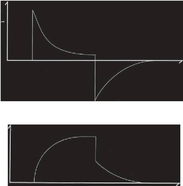
Figure 3.3
Generalized rock/soil charging and discharging current (after Hill, 1999)
CHARGING
CURVE
V
DISCHARGING
CURVE
TIME
Figure 3.4
Generalized rock/soil charging/discharging potentials (after Hill, 1999)
current will change polarity, spike, and then decay to zero. This is shown
schematically in figure 3.3.
The potential difference between two potential electrodes (i.e., NOT the
two current electrodes) will rise asymptotically to some limiting value. If
the current is then cut off, the potential will drop sharply, to some inter-
mediate value and then decay exponentially to zero, as shown in figure 3.4.
The earth responses, shown in figures 3.3 and 3.4, are similar to that of a
capacitor in an electrical circuit and are indicative of (electrical) energy
storage (Hill, 1999).
Conrad Schlumberger first observed the phenomena shown in figures 3.3
and 3.4 and disclosed his observations in a 1912 German Patent (Sumner,
1976). Schlumberger named the phenomenon
polarisation provoquée
(
PP
),
which has the excepted translation of “Induced Polarization” (IP) in the geo-
physical community (Schlumberger, 1920; Sumner, 1976). Schlumberger


Search WWH ::

Custom Search