Civil Engineering Reference
In-Depth Information
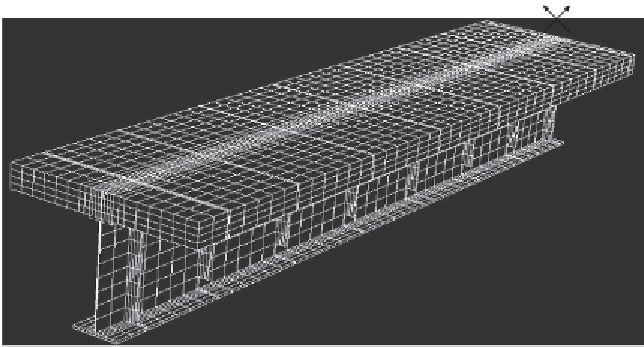
RC concrete slab
3
2
Vertical stiffener
Stud
connector
locations
1
Steel girder
Bearing location
Figure 7.2 Finite element mesh of composite beam G1.
type of concrete slab, diameter of stud, height of stud, strength of stud, and
concrete strength (see Section 5.6 of
Chapter 5
in this topic). Earlier exper-
imental and numerical investigations reported by the author [2.68,2.69] pro-
vided detailed information regarding the capacity and load-slip behavior of
headed stud shear connectors in composite girders with solid slabs. In this
dicted based on the detailed experimental and numerical investigations
[2.68,2.69]. Following the same approach [2.68,2.69], the load-slip charac-
teristic of the stud was inserted in the finite element model (
Figure 7.2
)
using
nonlinear springs in direction 2-2 at the location of the headed studs. On the
other hand, the vertical pressure between the concrete slab and the steel
beam was simulated by vertical rigid springs with high stiffness in direction
3-3 at the locations of the headed studs.
The steel plate girder-concrete slab interface was modeled by interface
elements available within the ABAQUS [1.29] element library. The method
requires defining two surfaces that are the master and slave surfaces. In
modeling the steel beam-concrete slab interface, the master surface within
the model was the top flange of the steel beam upper surface and the slave
surface was the bottom surface of the concrete slab. The interface elements
are formed between the master and slave surfaces and monitor the displace-
ment of the slave surface in relation to the master surface. When the two
surfaces remain in contact, the slave surface can displace relative to the


Search WWH ::

Custom Search