Civil Engineering Reference
In-Depth Information
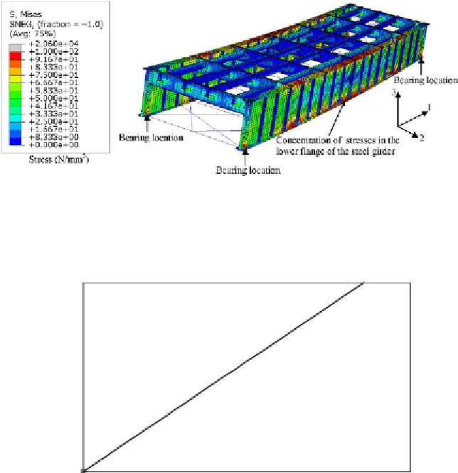
Figure 6.31 Stress (von Mises) contours under loading of the double-track open-timber
floor plate girder railway steel bridge (enlarged 10).
1
0.8
0.6
0.4
0.2
FE
0
0
5
10
15
20
25
30
35
40
Mid-span deflection (mm)
Figure 6.32 Load per one main girder-midspan deflection relationship obtained
numerically for the double-track open-timber floor plate girder railway steel bridge
under the live loading case.
deflection curve predicted numerically was plotted in
Figure 6.32
.
It can be
shown that the relationship is linear, which confirms that the deformations
were in the elastic range. The maximum deflection predicted after the appli-
cation of the live load case was 34.3 mm.
Let us now look at the deformed shape of the whole bridge analyzed to
failure and predicted using the RIKS method as shown in
Figure 6.33
.
It can
be seen that a clear combined lateral-torsional buckling mode of the upper
main plate girder flange and web buckling mode was predicted at midspan


Search WWH ::

Custom Search