Civil Engineering Reference
In-Depth Information
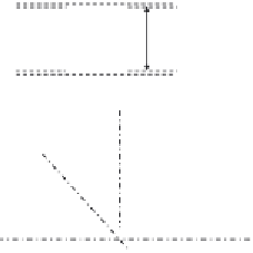
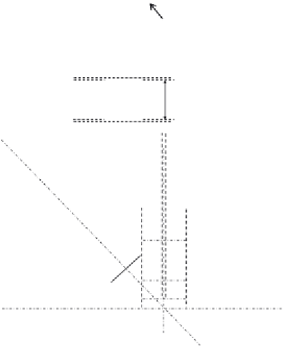
4.6.3.33 Design of Joint J
7
pretensioned bolts as follows.
Number of Bolts for the Vertical Member D
1
N
D
ðÞ¼
F
Ed
6203
9
206
¼
30
:
F
s
,
ult
¼
:
1 bolts, taken as 32 bolts (16 bolts in each side
acting in double shear)
Number of Bolts for the Vertical Member V
2
N
V
ðÞ¼
F
Ed
F
s
,
ult
¼
1878
6
103
¼
18
:
:
2 bolts, taken as 20 bolts (10 bolts in each side
acting in single shear)
2 Flange plate = 260×34
Web plate = 392×24
JointJ
7
2 Flange plates = 260×30
2 Web plate = 300×20
260 mm
360 mm
260 mm
360 mm
360 mm
2 Flange plate = 260×20
Web plate = 320×10
Cover plate = 500×10
2 Web plate = 400×10
Lower flange plate = 360×10
360 mm
V
6
360 mm
D
1
D
2
L
1
L
2
400 mm
400 mm
500 mm
500 mm
350 mm
Cover plate = 500×20
2 Web plate = 400×20
Lower flange plate = 360×20
400 mm
400 mm
500 mm


Search WWH ::

Custom Search