Civil Engineering Reference
In-Depth Information
h
i
+
l
2
51+
a l
0
F¼
0
:
:
2
¼
0
764
2
F¼
0
:
51+0
:
49 0
ð
:
764
0
:
2
Þ
+0
:
:
888
1
w¼
888 +
p
¼
0
:
746 but
w
1
:
0
888
2
764
2
0
:
0
:
0
:
0
:
746
27,600
275
1
Then,
N
b
,
Rd
¼
¼
5,147,400N
:
1
N
b
,
Rd
¼
5147
:
4kN
>
N
Ed
¼
4706
:
6 kN ThenO
ð
:
K
:
Þ
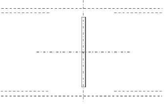
4.6.3.21 Design of the Compression Diagonal Member D
4
a compressive design force of
1935.7 kN can be designed as follows.
To classify the cross section chosen (see
Figure 4.203
)
,
s
235
f
y
r
235
275
e ¼
¼
¼
0
:
924
C
1
¼
115mm,
t
fl
¼
26,
C
1
=
t
fl
¼
115
=
26
¼
4
:
4
<
30
:
5 Flange is Class 1
ð
Þ
C
2
¼
292mm,
t
w
¼
14,
C
2
=
t
fl
¼
292
=
14
¼
20
:
9
<
30
:
5 Web is Class 1
ð
Þ
32 cm
2
A¼
2
26
2
:
:
8
1
:
4
¼
178
:
6+30
¼
48,731 cm
4
8
3
6
26
3
7
2
I
x
¼
1
:
4
30
:
=
12 + 2
2
:
=
12 + 2
:
6
26
16
:
6
26
3
4
3
12
¼
7623 cm
4
I
y
¼
2
2
:
=
12 + 30
:
8
1
:
=
r
I
x
A
r
48,731
178
i
x
¼
¼
¼
16
:
53 cm
:
32
26 cm
y
2.6
x
x
1.4
2.6
y
Figure 4.203 The cross section of the diagonal compression member D
4
.


Search WWH ::

Custom Search