Civil Engineering Reference
In-Depth Information
wAf
y
g
M1
where
N
b
,
Rd
¼
1
F
+
w¼
p
but
w
1
:
0
l
2
F
2
h
i
+
l
2
51+
a l
0
F¼
0
:
:
2
¼
0
365
2
F¼
0
:
51+0
:
34 0
ð
:
365
0
:
2
Þ
+0
:
:
595
1
w¼
595 +
p
¼
0
:
939 but
w
1
:
0
:
:
595
2
0
:
365
2
0
0
:
939
232
:
4
275
0
Then,
N
b
,
Rd
¼
¼
5,455,590N
1
:
1
N
b
,
Rd
¼
5455
:
>
N
Ed
¼
4846
:
ð
:
:
Þ
6kN
8 kN Then O
K
4.6.3.14 Design of the Lower Chord Member L
4
and L
5
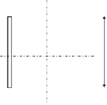
Let us now design the tensile lower chord members L
4
and L
5
, shown in
Figure 4.194
, carrying a tensile design force of 11,039.3 kN. To assume a
reasonable cross section for the lower chord tension members, the following
parameters can be considered:
L
12
30
¼
5000
12
30
¼
417
166mm,
h ¼
taken as 400 mm
:
Once again, it should be noted that the gusset plates must be spaced at a
constant distance (
b
) of 400 mm. Let us start by assuming the flange and web
thickness of 26 mm (see
Figure 4.194
)
. It should also be noted that the gross
b
= 36 cm
2.6
y
x
x
2.6
2.6
y
2.6
50 cm
Figure 4.194 The cross section of the lower chord tension members L
4
and L
5
.


Search WWH ::

Custom Search