Civil Engineering Reference
In-Depth Information
4
4
A
A
10 m
10 m
10 m
20 m
20 m
g
vk
= 77.1 kN/m
450 kN
450 kN
q
vk
= 45.65 kN/m
1.2 m
-
0.76
1.0
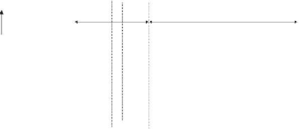
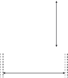
Figure 4.190 Determination of the compression force in vertical member V
4
using the
influence line method.
J
1
J
2
J
3
J
4
J
5
−4846.8
−4846.8
−10366.4
−10366.4
3284.3
6203.9
−4706.6
−1878.6
−1878.6
−4433.9
−4433.9
J
6
J
11
J
7
J
8
J
9
J
10
8302.3
8302.3
11039.3
11039.3
4433.9 kN
4433.9 kN
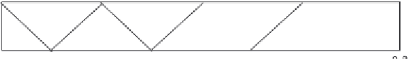
Figure 4.191 Distribution of forces in the W-shaped main truss under the dead and live
cases of loading.
50 cm
3.6
C = 34
e
= 3.74
x
x
m
m
2.4
2.4
3.6
2.4
Gusset plate
b
= 36
Figure 4.192 The cross section of the maximum compression members U
4
and U
3
.


Search WWH ::

Custom Search