Civil Engineering Reference
In-Depth Information
5000
U
1
U
2
U
3
U
4
U
5
4000
D
1
D
3
V
1
V
2
D
2
V
3
V
4
V
5
D
4
S
1
S
1
S
2
L
2
L
3
L
5
L
1
L
4
S
2
8 × 5000 = 40,000 mm
Elevation
5000
5000
8 × 5000 = 40,000 mm
Upper wind bracing (section
S
1
-
S
1
)
5000
5000
8 × 5000 = 40,000 mm
Lower wind bracing (section
S
2
-
S
2
)
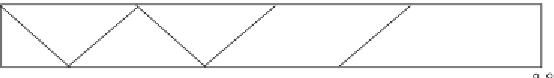
Figure 4.163 General layout of a deck truss highway steel bridge (the fifth design
example).
Dead Loads
The general layout of an intermediate stringer is shown in
Figure 4.164
. The
dead loads acting on an intermediate stringer can be calculated as follows:
¼
1
m
2
Flooring 1
:
75 kN
=
:
75
2
¼
3
:
5kN
=
m
Reinforced concrete slab deck 0
ð
:
2m thickness
Þ ¼
5
2
¼
10 kN
=
m
Haunch Equivalent to 1 cm slab thickness
ð
Þ ¼
0
:
25
2
¼
0
:
5kN
=
m
Own weight of stringer
¼
1
:
5kN
=
m


Search WWH ::

Custom Search