Civil Engineering Reference
In-Depth Information
4
4
6
14
4
17
7
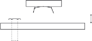
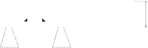
Figure 4.161 The designed roller and hinged line rocker fabricated steel bearings.
longitudinal and lateral directions of the bearing base, respectively. Similar to
the roller bearing, the material of construction for the bearings is cast iron
steel (ISO 3755) 340-550 having a yield stress of 340 MPa and an ultimate
stress of 550 MPa. It should be noted that the overall height of the hinged
bearing must be exactly the same as that of the roller bearing. The general
layout and assumed dimensions of the hinged line rocker bearing are shown
as follows:
Q
lak
¼
33
L
a
,
b
¼
33
27
¼
991 kN
1000 kN
½
,
for Load Models 71
Q
lbk
¼
20
L
a
,
b
¼
20
27
¼
540
6000 kN
½
,
for Load Models 71,SW
=
0,SW
=
2 and HSLM
for the direction of the forces). Also, the reaction from the lower wind brac-
culated as follows:
6kN
We can now determine the normal stress distribution due to the applied
loads, shown in
Figure 4.160
,
on the concrete foundation as follows:
R
tot
¼
381
:
N
A
M
x
I
x
y
M
y
I
y
x
f ¼
N
A
¼
3,132,800
950
1100
¼
3
:
0MPa
M
x
I
x
y ¼
381
240
950
1100
3
:
6
10
3
550
¼
0
:
49MPa
=
12
1431
10
3
M
y
I
y
x ¼
240
1100
950
3
12
475
¼
2
:
08MPa
=


Search WWH ::

Custom Search