Civil Engineering Reference
In-Depth Information
Q
D+L+
f
=
1325 kN
N
4
N
3
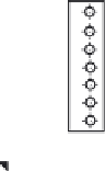
Figure 4.156 The connection between cross girder and main plate girder.
Field splice position
Field splice position
7500
6500
6500
7500
5750
16,500
5750
6×4500=27,000 mm
28,000 mm
Figure 4.157 Positions of field splices in the main plate girder.
compensated by three flange splice plates having cross-sectional area of
54
1.6 and 2
25
1.6 cm
2
with a total area of 166.4 cm
2
, which is
greater than the original area, while the area of web pla-
te
¼
270
1.6
¼
432 cm
2
can be compensated by two web splice plates hav-
ing cross-sectional area of 2
260
1.0 cm
2
with a total area of 520 cm
2
,
which is governed by the minimum thickness (10 mm) of plates used in rail-
way steel bridges. The top row of bolts in the web (see
Figure 4.158
)is


Search WWH ::

Custom Search