Civil Engineering Reference
In-Depth Information
X.G. web
X.G. web
100 kN
Stringer web
s
Fsin
a
s
100 kN
180 cm
Plan
F
Fcos
a
Stringer web
150 cm
150 cm
150 cm
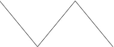
Figure 4.150 Analysis of forces acting on the lateral shock bracing.
y
x
x
Bracing cross section
s
-
s
2 angles back-to-back
80 × 80 × 8
10 mm
y
Figure 4.151 The cross section of the lateral shock bracing members.
member can be determined from designing the critical diagonal member for
the compressive force as follows:
Assume the cross section of the stringer bracing as 2 angles back-to-back
a¼
tan
1
1
:
8
2
5
¼
50
:
1
:
l
b
¼
2343mm
r
235
275
e ¼
¼
0
:
924
L
cr
i
1
l
1
l¼


Search WWH ::

Custom Search