Civil Engineering Reference
In-Depth Information
250 250
250 250 kN
Case of loading 1
q
vk
= 80 kN/m
q
vk
= 80 kN/m
A
B
11.1
9.5
0.8
1.6
1.6
1.6
0.8
27.0 m
I.L. for
B.M.D.
4.75
5.15
5.55
5.95
5.95
6.7
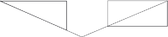
Figure 4.139 Determination of the maximum bending moment on one main plate
girder due to live loads using the influence line method (case of loading 1).
250 250 250 250 kN
Case of loading 2
q
vk
= 80 kN/m
q
vk
= 80 kN/m
A
B
a
1.6
10.7
9.9
0.8
1.2
1.6
0.8
0.4
27.0 m
Y
A
= 1316.8 kN
Y
B
= 1331.2 kN
Figure 4.140 Determination of the maximum bending moment on one main plate
girder due to live loads using the analytical method (case of loading 2).
loads and the closest load, with maximum bending moment located at the
closest load (point a in
Figure 4.140
). The maximum bending moment
under the first case of loading is calculated using the influence line method
(by multiplying the concentrated loads by the companion coordinates on the
bending moment diagram and by multiplying the distributed loads by
the companion areas on the bending moment diagram), while that under
the second case of loading is calculated analytically using structural analysis.
Hence, the bending moments due to live loads can be calculated as follows:
M
L
:
L
:
ð
case of loading 1
Þ ¼
250
5
½
:
95 + 6
:
75 + 5
:
95 + 5
:
15
+80
0
:
5
9
:
5
4
:
75 + 80
0
:
5
11
:
1
5
:
55
¼
10,219
:
2kNm


Search WWH ::

Custom Search