Civil Engineering Reference
In-Depth Information
1
2
1
25
26
2
F
w
¼
:
5
:
7
208
:
25
¼
501,518N
¼
501
:
5kN
Considering the structural analysis for the upper wind bracing system
shown in
Figure 4.118
, the critical design wind force in the diagonal bracing
members can be calculated as follows:
Distributed wind loads
q
WL
ð
Þ¼
501
:
5
0
:
5
=
48
¼
5
:
22 kN
=
m
Factored distributed wind loads
¼ q
WL
g
q
¼
5
:
22
1
:
7
¼
8
:
87 kN
=
m
R
A
¼
8
:
87
24
¼
212
:
9kN
a¼
tan
1
2
8
ð
:
5
=
3
Þ
39
:
6kN
The cross section of the bracing member (see
Figure 4.119
) can be deter-
mined as follows:
l
b
x
¼
3910mm,
F
D
¼
212
:
9
=
ð
sin30
:
8
Þ
332
:
2
3910
¼
4690mm
Choose two angles back-to-back 100
100
10, with 10 mm gusset
plate between them:
A¼
2
19
l
b
y
¼
1
:
4cm
2
,
:
2
¼
38
:
i
x
¼
3
:
05 cm,
e ¼
2
:
83 cm,
q
3
2
05
2
+2
i
y
¼
:
ð
:
83 + 0
:
5
Þ
¼
4
:
52 cm
r
235
275
e ¼
¼
0
:
924
L
cr
i
1
l
1
l¼
l
1
¼
93
:
9
0
:
924
¼
86
:
7636
3910
30
1
l¼
7636
¼
1
:
478
:
5
86
:
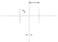
e
= 28.3 mm
y
x
x
2 angles back-to-back
100 × 100 × 10
10 mm
y
Figure 4.119 Lower wind bracing cross section.


Search WWH ::

Custom Search