Civil Engineering Reference
In-Depth Information
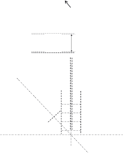
2 Flange plate = 350 × 14
Web plate = 372 × 10
Joint J
12
2 Flange plate = 350 × 14
Web plate = 372 × 10
350 mm
400 mm
350 mm
350 mm
2 Flange plate = 350 × 10
Web plate = 380 × 10
Cover plate = 550 × 22
2 Web plate = 450 × 22
Lower flange plate = 400 × 22
400 mm
400 mm
V
6
D
5
D
6
L
5
L
6
450 mm
450 mm
550 mm
350 mm
Cover plate = 550 × 22
2 Web plate = 450 × 22
Lower flange plate = 400 × 22
400 mm
450 mm
550 mm
Figure 4.104 Details and drawings of the main truss joint J
12
.
4.4 DESIGN EXAMPLE OF A HIGHWAY STEEL-CONCRETE
COMPOSITE BRIDGE
The third design example presented in this chapter is for a highway steel-
concrete composite bridge. The general layout of the through bridge is
shown in
Figures 4.106
and
4.107
, with a brief introduction to the bridge
components previously explained in Figure 1.22. The steel-concrete com-
posite bridge has simply supported ends with a length between supports of


Search WWH ::

Custom Search