Civil Engineering Reference
In-Depth Information
Then,
F
s,Rd
¼
117 kN (for bolts in single shear at serviceability limit
states) and
F
s,Rd
¼
234 kN (for bolts in double shear at serviceability limit
states). At ultimate limit states,
F
s,Rd,ult
can be calculated as follows:
1
:
0
1
:
0
0
:
4
F
s
,
Rd
,
ult
¼
320,880
¼
102,682N
:
1
:
25
Then,
F
s,Rd
¼
103 kN (for bolts in single shear at ultimate limit states)
and
F
s,Rd
¼
206 kN (for bolts in double shear at ultimate limit states):
604
5
206
¼
2
:
N
1
¼
:
9 taken as 3 bolts,
:
604
5
103
¼
5
N
2
¼
:
9 taken as 6 bolts
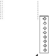
4.3.3.31 Design of Cross Girder-Main Truss Connection
The cross girder is designed as a simply supported beam on main trusses;
therefore, once again, the connection is mainly transferring shear forces
(maximum reaction from cross girders of 1600.8 kN) (see
Figure 4.86
)
.
We can determine the required number of bolts as follows:
:
1600
8
206
¼
7
N
3
¼
:
8 taken as 8 bolts,
1600
8
103
¼
15
:
N
2
¼
:
5 taken as 16 bolts
4.3.3.32 Design of Wind Bracings
Wind forces acting on the investigated through highway bridge (see
Figure 4.87
) as well as any other lateral forces directly applied to the bridge
Q
D+L+
f
= 1600.8 kN
N
3
N
4
Figure 4.86 The connection between a cross girder and the main truss.


Search WWH ::

Custom Search