Civil Engineering Reference
In-Depth Information
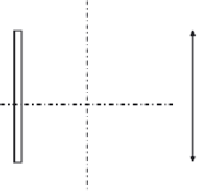
b
= 40
2.2
y
x
x
2.2
2.2
y
2.2
55 cm
Figure 4.81 The cross section of the lower chord tension member L
5
.
section for the lower chord tension members, the following parameters can
be considered:
L
15
30
¼
6000
12
30
¼
500
200mm, taken as 450 mm
h ¼
:
Once again, it should be noted that the gusset plates must be spaced at a
constant distance (
b
) of 400 mm. Let us start by assuming the flange and web
thicknesses of 22 mm (see
Figure 4.71
). It should also be noted that the gross
and net cross-sectional areas of the lower chord members are the same since
they are connected using butt weld. The design of section can be performed
adopting the same procedures used for the diagonal tension members as
follows:
2
¼
407 cm
2
A¼A
net
¼
55
2
:
2+40
2
:
2+2
45
2
:
Af
y
g
M0
¼
407
275
100
1
N
pl
,
Rd
¼
¼
11,192,500N
¼
11,192
:
5kN
>
N
Ed
:
0
¼
11,165
:
7kN
0
:
9
A
net
f
u
g
M2
¼
0
:
9
407
100
430
1
N
u
,
Rd
¼
¼
12,600,720N
¼
12,600
:
7kN
:
25
>
N
Ed
¼
11,165
:
7kN
4.3.3.27 Design of the Lower Chord Member L
4
Following the same procedures adopted for the design of the lower chord
member L
5
, we can design the tensile lower chord member L
4
, shown in


Search WWH ::

Custom Search