Civil Engineering Reference
In-Depth Information
35 cm
y
2
x
x
1.2
2
y
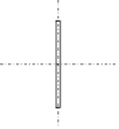
Figure 4.78 The cross section of the diagonal tension member D
3
.
Af
y
g
M0
¼
183
:
2
275
100
1
N
pl
,
Rd
¼
¼
5,038,000N
¼
5038 kN
>N
Ed
:
0
¼
4086
:
1kN
0
:
9
A
net
f
u
0
:
9
135
:
2
430
N
u
,
Rd
¼
g
M2
¼
¼
4,185,792N
1
:
25
¼
4185
:
8kN
>
N
Ed
¼
4086
:
1kN
4.3.3.24 Design of the Diagonal Tension Member D
2
tensile design force of 5372.3 kN can be designed as follows:
The bolts used in connecting the member with gusset plates are M27
high-strength pretensioned bolts having a clearance of 3 mm (hole diameter
Ø
¼
30 mm):
92 cm
2
A¼
2
35
2
:
8+34
:
4
1
:
8
¼
257
:
72 cm
2
A
net
¼
257
:
92
8
3
:
0
2
¼
190
:
35 cm
y
2.8
x
x
1.8
2.8
y
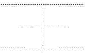
Figure 4.79 The cross section of the diagonal tension member D
2
.


Search WWH ::

Custom Search