Civil Engineering Reference
In-Depth Information
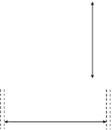
55 cm
2.4
C
= 40.2
e
= 3.53
x
x
m
m
1.6
1.6
2.4
2
.4
Gusset plate
b
= 40
Figure 4.69 The cross section of the compression member U
2
.
s
235
f
y
r
235
275
e ¼
¼
¼
0
:
924
b ¼
400mm,
t
fl
¼
24,
b
=
t
fl
¼
400
=
24
¼
16
:
<
:
ð
Þ
7
30
5 Flange is Class 1
C ¼
402mm,
t
w
¼
16,
C
=
t
fl
¼
402
=
16
¼
25
<
30
:
5 Web is class 1
ð
Þ
6
¼
372 cm
2
A¼
55
2
:
4+40
2
:
4+2
45
1
:
55
2
:
4
23
:
7
40
2
:
4
18
:
9
e ¼
¼
3
:
53 cm
372
6
45
3
4
3
7
2
I
m
¼
2
1
:
=
12 + 55
2
:
=
12 + 55
2
:
4
23
:
¼
132,844
4
3
9
2
7cm
4
+40
2
:
=
12 + 40
2
:
4
18
:
:
53
2
2cm
4
I
x
¼
132,844
:
7
372
3
:
¼
128,209
:
4
55
3
4
40
3
6
3
8
2
I
y
¼
2
:
=
12 + 2
:
=
12 + 2
45
1
:
=
12 + 45
1
:
6
20
:
9cm
4
¼
108,405
:
r
I
x
A
r
128,209
:
2
i
x
¼
¼
¼
18
:
56 cm
372
r
I
y
A
r
108,405
:
9
i
y
¼
¼
¼
17
:
07 cm
372
l
b
x
¼ l
b
y
¼
6000mm


Search WWH ::

Custom Search